System Overview
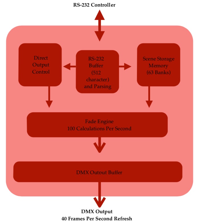
The RS-232 DMX Engine is a self-contained DMX controller. It accepts simple, human-readable commands via RS-232 and uses these commands to generate, recall and crossfade between DMX scenes. Incoming serial data is buffered in the system’s memory until a carriage return is received, which signifies the end of a command.
Once the command has been received, it is parsed. Commands containing syntax errors are ignored, and an error message is transmitted back to the RS-232 host. Valid commands are processed immediately.
Commands can contain information directing the system to
-
Set DMX channels to certain levels. The entire universe of 512 channels is available.
-
Store scenes (a snapshot of the DMX output buffer) in memory.
-
Recall scenes from memory using a very simple command syntax.
-
Fade between different scenes. The system automatically calculates all intermediate DMX
channel values, and requires only a crossfade time from the end user.
-
Report the state of any DMX channel back to the user via RS-232.
More significantly, commands may be processed simultaneously, with the only limit being (a) the RS-232 port speed and (b) the 512-byte receive buffer. This means that, for example, a group of channels can fade between levels at one rate while a second group of channels can fade to different levels at a completely different rate.
Users of high-end theatrical lighting consoles may recognize this feature as ‘simultaneous cue stacks,’ and it adds a great deal of flexibility to the system’s operation.
Power Supply
9-15v DC, 200 mA, center positive. Barrel size is 2.1 x 5.5 mm. System ships with a switching power supply, 9V DC output, 300 mA, 80-240V AC input. It will work worldwide, though an adapter for the two-pin American-style plug may be required. Check a travel shop, or ask at a hotel’s front desk if they have any in Lost & Found.
DMX Output
Standard XLR pinout per USITT. We use only official Neutrik XLR jacks.
-
Pin 1 ground
-
Pin 2 Data -
-
Pin 3 Data +
-
Pins 4 & 5, of XLR5 jack is installed are not connected
-
Each DMX output is driven by its own transmitter.
Serial Command Protocol
Baud Rate: 9600, 19,200, 38,400, 57,600 or 115,200, 8N1, user selectable. Default is 115,200.
-
Pin 2 is system transmit
-
Pin 3 is system receive
-
Pin 5 is ground
DB-9 connector pin 4 (DTR) is used to update the system’s firmware. This allows new features to be added in the field, without requiring the hardware to be shipped back to our shop. If asserted (set high) by the PC or other controlling equipment, the system will wait in ‘reset’ mode for new firmware and the system will neither accept serial commands nor output DMX. In normal use, either physically disconnect this wire or ensure that DTR is cleared.
Depending on which external devices is sending the RS-232 data, a crossover cable (which swaps pins 2 & 3) may be required. When connected directly to a PC, a ‘straight’ cable works properly.
In the following pages, the text [cr] is used to represent a single data byte, the carriage return. This value is decimal 13 or hex 0x0D.
Many screenshots show data sent / received through a terminal program, as well as a screenshot from a DMX monitoring program. Data sent from the PC to the system is displayed in green text, and data generated by the system is yellow. Thus, system output can be easily compared with RS-232 input.