Command Syntax
Here's how to talk with the box.
- Overview
- Group Command
- Build a New Scene (F)
- Build A Scene (A)
- Jog a Channel
- Store a Scene
- Recall a Scene
- Set Startup Scene & Timeout Delay
- Selectable DMX Output Speed
- Query DMX Channel Values
- Automatic Color Wheel
- Clear all Channels
- Set System Baud Rate
- Software Reset
- Streaming Mode
Overview
In the following pages, the text [cr] is used to represent a single data byte, the carriage return. This value is decimal 13 or hex 0x0D. All commands are terminated with a carriage return.
Also, in the following pages some syntax may be provided in code blocks, like this:
This is code in a block.
It's how our online markdown language calls out this type of text.

--! Note the grey '1' and '2', etc in the far left column. !--

These are line numbers for reference only. Don't include
them in actual commands!

Some sample real RS-232 commands just for reference:

C[cr]
G0@255:0[cr]
G1-10@100,11@238:35[cr]
B115200[cr]
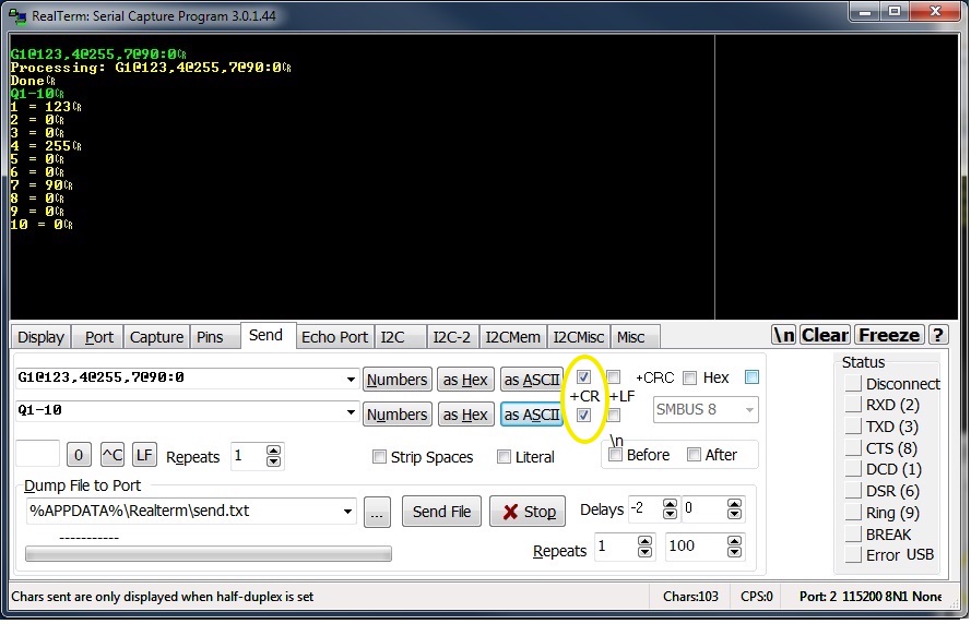
Group Command
If you're starting from scratch, most of the engine's functionality can be accessed through the G command. It doesn't require leading zeros like 'A' or 'F' and includes other syntax for controlling large groups of channels in a single command.
Occasionally it is useful to set a large group of DMX channels to the same level. While this can be accomplished using the standard ‘F’ or ‘A’ commands, the new ‘G’ command allows the channels to be adjusted in a less verbose way.
GA-B@C:T[cr]This command sets channels in range [A B] to value C and crossfade time T. A and B are valid between [1 512] and leading zero is not required. C is the channel value, range [0 255]. T is the time, in tenths of a second, for the crossfade to take place. Range for T is [0 999] or 99.9 seconds maximum.
Example: Set DMX channels 37 - 126 to 50% over 7.6 seconds:
G37-126@127:76[cr]Or, set every 'S'th channel to a level. This is useful if, perhaps, there are multiple RGB LED tape dimmers in a single room, and you'd like to set all of the red channels to the same value:
GA-B/S@C:T[cr]As above, but the slash and S allows for a group of channels in a particular pattern to be set. For example, if a group of RGB fixtures had sequential start addresses (1, 4, 7, 10...) the red channel in each fixture could be controlled easily, skipping through the array.
Example:
5 RGB fixtures are sequentially connected, and the first start address is 100. Turn on all the green and blue elements over 2.5 seconds:
G101-114/3@255:25[cr]  <--- this sets channel 101, 104, etc which is probably RED
G102-114/3@100:25[cr] <--- this sets channel 102, 105, etc which is probably GREEN|
Fixture # |
Channel |
Value (Red) |
Channel |
Value (Green) |
Channel |
Value (Blue |
|
1 |
100 |
0 |
101 |
255 |
102 |
100 |
|
2 |
103 |
0 |
104 |
255 |
105 |
100 |
|
3 |
106 |
0 |
107 |
255 |
108 |
100 |
|
4 |
109 |
0 |
110 |
255 |
111 |
100 |
|
5 |
112 |
0 |
113 |
255 |
114 |
100 |
Finally, multiple sub-commands can be chained together in the same command, separated by commas and ending with a fade time. As above, the syntax is Gchannel@value,channel@value...channel@value:time[cr]
G1@255,3@127,12@10,27@255:24[cr]Secret shortcut: Using 0 as the channel is the same as 'all call', or channels [1 512]. An easy way to turn on all connected equipment for a sanity check is to use a command like G0@255:0[cr] or perhaps G0@0:0[cr].
Build a New Scene (F)
Building a New Scene
This command is useful but tricky. ANY CHANNEL not specifically called out in a control string is set to zero. If you're starting from scratch or writing your own driver, in general it's easier to use the A (add) command or G (group) command instead. However, there are legacy systems out there with programming based on F, so it's included here for reference.
A common tech support call has the gist of "I sent a command and it worked perfectly, then I sent a second command and all the first lights turned off. What's wrong?" Don't use F unless you know exactly what you're doing.
                          FXXX@YYY:TTT[cr]
                  FXXX@YYY,AAA@BBB,CCC@DDD:TTT[cr]
-
F is a capital F
-
@ is the ASCII 'at' character, hex 0x40
-
XXX, AAA, CCC are three digit DMX channel numbers with range [001 512]. As only channels
1-512 exist in a typical DMX universe, channel 000 can used to select all channels.
-
YYY, BBB, DDD are three digit channel values with range [000 255] (:) is the ASCII colon character,
hex 0x3A
-
TTT is a three digit time value, in tenths of a second, range [000 999]
-
[cr] is the carriage return character, decimal 13 or hex 0x0D.
For example, following the completion of these (one with a zero fade time, one with 2.4 seconds and one with 1.0 second crossfades):
F001@100:000[cr]
F010@128,011@127,012@126:024[cr]
F007@010:010[cr]
... the DMX output buffer would have the following values:
CH1 - CH6: 0
CH7: 010
CH8-CH512: 0
Build A Scene (A)
The A command allows new channel:value combinations to be stacked on the existing DMX output universe. This command adds to what's currently being output. In Photoshop, it's similar to creating a new layer. Nothing below is affected, the A command just adds new channel:value information to the existing scene.
If you're starting from scratch or building your own driver, use the G (group) command instead. It's easier to design with because leading zeroes are omitted and the syntax is more powerful.
AXXX@YYY:TTT[cr]
AXXX@YYY,AAA@BBB,CCC@DDD:TTT[cr]-
A is a capital A
-
XXX, AAA, CCC are three digit DMX channel numbers with range [001 512]
-
YYY, BBB, DDD are three digit channel values with range [000 255]
-
TTT is a three digit time value, in tenths of a second, range [000 999]
-
For ‘A’ commands, the channel:value information contained in each string adds to data in the DMX output buffer. Higher values take precedence. Thus, lighting data may be added to existing scenes a few channels at a time. In a photo editing application, this process would be similar to adding layers to an image.
-
Leading zeros are required.
If a channel is not specifically mentioned in an A command, its value remains the same as it as before the command was processed.
If the following commands were transmitted:
F001@100:000[cr]
A002@255:000[cr]
A010@128,011@127,012@126:024[cr]
A007@010:010[cr]
... the DMX output buffer would have the following values:
CH1 : 100
CH2 : 255
CH10 : 128
CH11 : 127 CH12 : 126 CH7 : 10
Jog a Channel
Individual DMX channels may be jogged up and down. In this mode, it is not required to know the channel’s exact value. Rather, it can be added to or subtracted from in arbitrary amounts, up to the limits of 0 or 255. This command may be useful when implementing bump buttons on a human interface control panel.
If a channel is jogged past the maximum or minimum values allowed in DMX, the command is ignored.
JN:X[cr]
JN:-X[cr]
JN:+X[cr]
- J is a capital J
-
N is the DMX channel number, range is [1 512]
-
X is a decimal number, either positive or negative, range [1 255]
-
[cr] is a carriage return.
Store a Scene
Up to 63 DMX scenes may be saved in memory. A scene is a copy of the current DMX output buffer. This memory is permanent and will survive a power cycle.
Typically, a group of 'G, ‘F’ or ‘A’ commands will be used to build a particular lighting scene. Once the desired look has been achieved, it can be stored in memory for future use. This greatly reduces programming and execution time.
There are no write protect settings. Any scene may be, at any time, re-recorded with an M command. Previously stored data in that memory bank will be replaced.
MXXX[cr]
For example, following the completion of these commands:
F001@100:000[cr]
A002@255:000[cr]
A010@128,011@127,012@126:024[cr]
A007@010:010[cr]
M22[cr]
... the DMX output buffer would have the following values:
CH1 : 100
CH2 : 255
CH10 : 128
CH11 : 127
CH12 : 126
CH7 : 10
...
and memory bank #22 may be recalled at any time in the future.
Recall a Scene
Recalling a Stored Scene
SXXX:TTT[cr]
-
S is a capital S
-
XXX is the desired scene number, valid range is [1 063]
TTT is the scene crossfade time, valid range is [000 999] tenths of a second
Up to 63 DMX scenes may be saved in memory. This memory is permanent and will survive a power cycle. Scenes may be recalled from memory and faded in over a specific time. Scene recall commands overwrite the DMX output buffer with stored data. Using this basic command, all channels are changed from their ‘live’ value to that which was stored in memory.
Example: recall stored scene #1 instantly:
S001:000[cr]
Example: crossfade from the current DMX output buffer with the contents of scene 32 over 5.7 seconds:
S032:057[cr]
However, in some instances it is desirable to recall a stored scene, but only apply it to part of a DMX universe. For example, consider a three-room home automation installation. Each room uses 15 channels of DMX for RGB accent lighting. It might be useful to recall a scene but only apply that data to a specific range of DMX channels. One room can change color while leaving the other rooms unaffected.
For that purpose, the S command can be overloaded with mask values:
SXXX:TTT,L,H[cr]
In this case, L and H represent the lower and upper bounds of the DMX channel range to be copied from system memory to the constantly repeating DMX output buffer. Other valid commands could include:
S6:030[cr] Recall scene six, three second crossfade.
S6:030,10,30[cr]As above, but only copy channels between 10 and 30 from memory to the DMX output buffer.
S6:000,100,150[cr] As above, but only copy channels 100-150 from memory to output. All other channel information carries through. Zero fade time.
Set Startup Scene & Timeout Delay
It may be useful for the DMX engine to auto-load a stored scene immediately after a power cycle. Often a control system may take tens of seconds, or even several minutes, to restore its state after an unplanned outage. For this reason, the DMX Engine can load a pre-saved scene immediately after power is applied.
Syntax
UX,T[cr]
U?[cr]
Examples
U1,5[cr] Load scene #1 five seconds after a power cycle
U0,0[cr] Change to zero startup scene. All DMX channels are zero until the connected equipment (Crestron, AMX, Control4, etc) sends commands:
Where
-
U is a capital U
-
X is the pre-saved scene number, [0 60]. Leading zeros not required.
-
If X = 0, no scene will load and system will run normally. The default startup behavior is to set all
channels to zero. If X is set to zero, T should be zero as well.
-
X is followed by a comma [,]
-
T is the approximate time, in seconds, the system will wait after startup to load the scene. DMX
output will be live and the system will respond to commands during this period. If any regular serial command is received during this time, the startup scene will not be recalled. Value here is [0 255], leading zeroes not required.
-
[cr] is a carriage return, hex $0D or decimal 13.
-
U?[cr] queries the startup scene status, and an ASCII string is returned to the user.
Notes:
-
Prior to defining a startup scene, the scene should be built and stored using the regular 'G', ‘F’ or ‘A’ commands, then stored with ‘S’.
-
An uninitialized scene will probably / possibly default to ‘all channels on.’ This is because a raw-
from-factory memory chip is loaded with ‘255’ or ‘0xFF’ as values. So be careful what you choose
to load without first pre-programming.
-
The timing value ‘T’ is approximate and may vary by +/- 10% or so.
Selectable DMX Output Speed
By default, the DMX engine transmits full-speed, full-frame DMX, and speeds close to the maximum available by the USITT spec. Unfortunately, we’ve learned that some DMX LED fixtures, particularly Amazon / eBay / Alibaba ‘bargain bin’ specials, have a hard time keeping up with this datastream.
To generate DMX with relaxed packet and inter-byte timing, ~ 15 frames per second, send the command:
Slow[cr] <--- that's a capital 'S' at the beginning, but the default font isn't super clear here.
For full frame DMX at ~40 frames per second, send the command:
Fast[cr]
The output speed command survives a power cycle. Immediately after a command is received, the system will reboot. The reboot process takes 2-3 seconds to complete. The DMX LED on the chassis will flash in sync with DMX packets, providing additional user feedback of the current setting.
For a more in-depth discussion of this issue, please visit www.response-box.com/gear/decabox-dmx-slowdowner/
Query DMX Channel Values
Sometimes it's useful to check the state of DMX channels..
QXXX-YYY[cr]
QA[cr]
- XXX has the range [1 512]
- YYY has the range [1 512]
- [cr] is the carriage return
Q100-100[cr]  <-- Query a single channel
Q70-35[cr]
Q35-70[cr]

QA[cr]  <-- Returns a list of all DMX channel:value combinations
This can take a while to transmit, depending on
system baud rate.
Automatic Color Wheel
This set of commands allows the DMX Engine to automatically cycle through an RGB color wheel, at a user-selectable speed. The wheel can be stopped at any time, or run indefinitely, and the DMX channels queried or an entire scene saved. This makes it easy for users to choose colors, or perhaps would allow a designer to run a rolling color cycle as a background effect, etc.
The color wheel has 512 steps total. Since the DMX Engine is generating all of the color intensities internally, the system controller (Control4, Crestron, etc) is free to perform other tasks.
Up to 20 x 3-channel RGB LED fixtures can be controlled simultaneously. This firmware release doesn’t specifically support LED fixtures which contain a ‘master intensity’ control, etc. However, those DMX channels can certainly be set on a channel-by-channel basis if needed, and then the color cycle can run on top of them. DMX channels not specifically mentioned in the RGB arrays (see below) are unaffected.
WRa,b,c,d[cr] ← Define the red array of channels, separated by commas.
WGa,b,c,d[cr] ← Define the green array of channels, separated by commas.
WBa,b,c,d[cr] ← Define the blue array of channels, separated by commas.
WTa[cr] ← Set the color wheel cycle time, in seconds.
WX[cr] ← Execute (start) the color wheel
WS[cr] ← Stop the color wheel
WC[cr] ← Clear color arrays, to allow reloading or change
W?[cr] ← Query the color system for DMX channels assigned to each color
These commands do not survive a power cycle, so they must be generated for each use. First, set an array of DMX channels corresponding to the red LEDs in each fixture. For example, assume six fixtures which are sequentially addressed. Their start addresses would be 1, 4, 7... Each fixture uses three channels, one each for red, green and blue. The arrays only need to be defined once per power cycle.
Example
Example:
First set the red channels:
WR1,4,7,10,13,16,19[cr]Then set the green channels:
WG2,5,8,11,14,17,20[cr]
WB3,6,9,12,15,18,21[cr]
Set the cycle time
Set the cycle time (for example, 12 seconds) with the command
WT12[cr]Once this is done, the color wheel can be started and stopped with
                               WX[cr]
                               WS[cr]
If the color wheel needs to be applied to one group of channels, and then a second group, the array can be set, stored and then re-set:
                       WR1,4,7,10,13,16,19[cr]
                       WG2,5,8,11,14,17,20[cr]
                       WB3,6,9,12,15,18,21[cr]
                               WT8[cr]
WX[cr]
... wait for the correct color to appear
WS[cr]
... store or otherwise manipulate the DMX scene perhaps using the 'M' command.
WC[cr]
WR22,25,28,31[cr]
WG23,26,29,32[cr]
WB24,27,30,33[cr]
WX[cr]
... wait for the new color to appear
WS[cr]
... store or otherwise manipulate the DMX scene
Clear all Channels
Pretty straightforward, this one. C for clear:
C[cr]Alternately, '0' in the G command as as channel number functions as all-call:
G0@X:0[cr] where X is [0 255]
G0@200:0[cr] set all to ~ 80%
G0@0:0[cr] another way to clear all channels
Set System Baud Rate
All standard RS-232 baud rates are supported. The change is stored in memory and naturally survives a power cycle. Default baud rate on new equipment is 115,200 8N1.
Baud rate is set at startup, so if it's changed using this command, power cycle the DMX Engine to activate the new setting.
B9600[cr]
B19200[cr]
B38400[cr]
B57600[cr]
B115200[cr]
All baud rates require require 8 data bits, 1 stop bit, no parity.
Software Reset
The result here is the same as if the box is power cycled. After a reset, the standard RS-232 'splash screen' is transmitted to any receiving equipment which cares to listen.
I[cr] <--- That's I as in Igloo or India

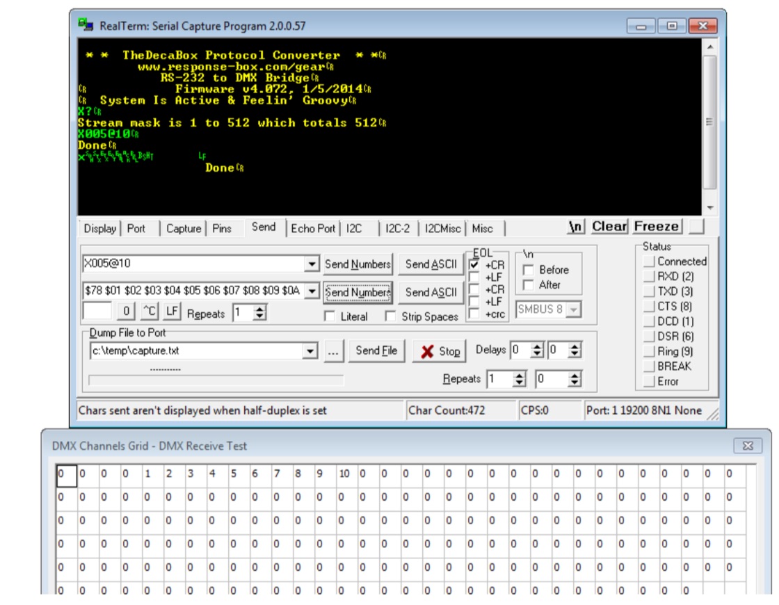
Streaming Mode
In this mode, it’s possible to transmit data directly to the DMX output buffer, with a bare minimum of protocol overhead.
The first step is to tell the system how many channels will be transmitted. This is called the ‘streaming mask.’ Since it may not be necessary or even desirable to control an entire universe at one time, a selection of channels may be chosen. The command is
X:LLL:SSS[cr]-
X is a capital X
-
LLL is a three digit lower-bound of the DMX range to control. Leading zeroes should be included.
-
SSS is the size of the mask, in DMX channels.
For example, to control channels 1-10
X:001:10[cr]... and to control channels 1-300
X:001:300[cr]To control channels 30-45
X:030:15[cr]A query command can also be sent:
X?[cr]The system will return the current channel mask. Default is [1 512] at powerup, and masks are not saved through a power cycle.
Once the range has been set, data can be sent directly to the serial port. Some care is required on the part of the user, however. A set of streaming data begins with the character ‘x’ and then is followed by binary bytes, the number of which corresponds to the channels being controlled.
When ‘x’ is received, the system begins counting subsequently-received bytes and storing them in a temporary buffer. When the appropriate number of bytes have been received, the temporary buffer is copied to the DMX output buffer. DMX channels which fall outside the streaming mask are unaffected.
Any number of streaming packets may be sent, provided that their length is sized appropriately. If more channels are sent than were originally specified, errors will be returned.
Here are a few examples.
For ease of reading on the printed page, $XX is used to denote a single binary byte, and whitespace is included here only for clarity.
Operate on DMX channels [5 13]
X005:8[cr]
Send 9 bytes total, which affect DMX channels 5-13
x $01 $02 $03 $04 $05 $06 $07 $08