Basic System Information
This firmware personality for the DecaBox receives MIDI note and CC information on a user-specified MIDI channel. This data is converted to DMX512 lighting data. In the standard firmware version, the first 128 DMX channels can be controlled in real time via MIDI.
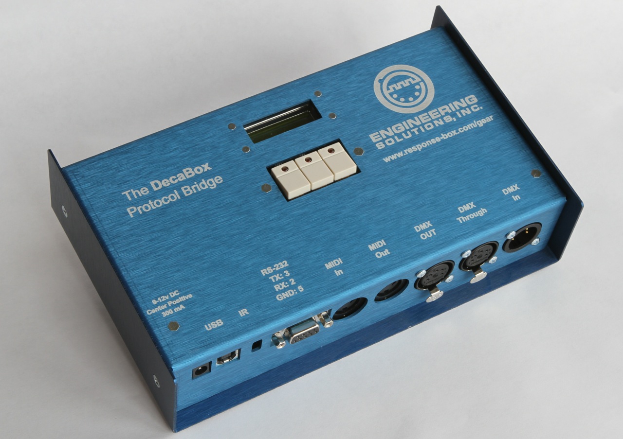
- The system ships with an international switching power supply. System power requirements are 9-12v DC, center positive, 300 mA. The power supply connector has standard dimensions of 2.1mm x 5.5mm.
- MIDI data is received via the 5 pin ‘MIDI In’ jack. MIDI data is passed through (a mirror of the input) via MIDI out.
- DMX lighting data is generated on the Neutrik 5 pin XLR female jack. If necessary, a 5 pin to 3 pin adapter cable may used to connect various lighting fixtures.
The DecaBox USB port is used for firmware updates. It does not accept MIDI data.
Other firmware builds are available which allow access to an entire universe of DMX data via MIDI. Contact Engineering Solutions for caveats and more information.
Originally, the lighting guys wanted to keep their wiring separate from the audio crew, who were using XLR-3 microphone cable; thus the 5 pin lighting data standard. However, in nearly every current implementation of DMX control only pins 1, 2 and 3 are used. The 5 pin connectors cost about $2 more in quantity, so some manufacturers eschew them for less expensive 3 pin versions. Professional and touring gear still relies nearly exclusively on the 5 pin infrastructure. In either case, pin 1 is ground, pin 2 is ‘data complement’ or D- and pin 3 is ‘data true’ or D+. For even more gory detail, see the appendix.